
Frontier models can (sometimes) plan how to machine simple parts
A weekend experimenting with AI machining planning


Over the weekend, I (Andy) made a proof of concept eval to test frontier model capabilities in understanding and working from engineering drawings. You might care about this because:
For an industrial explosion to follow an intelligence explosion, you need things to change in the physical world. Understanding how well frontier models grok drawings and machining could help us understand how physical R&D will be accelerated
Almost every precision-machined part in production has an engineering drawing (or Model Based Definition; the digital equivalent). Understanding the concepts they convey is currently a fundamental prerequisite to building functional products and machines.
Interpreting an engineering drawing requires both multi-step reasoning, planning, and understanding geometries.
It wasn’t obvious to me that the models would be good at this
Some context about me: I’m a mechanical engineer and Co-Founder of Amodo. I’ve spent a lot of time designing parts, building prototypes, and teaching engineers to build hardware. I’ve also spent a lot of time thinking about AI safety & capabilities.
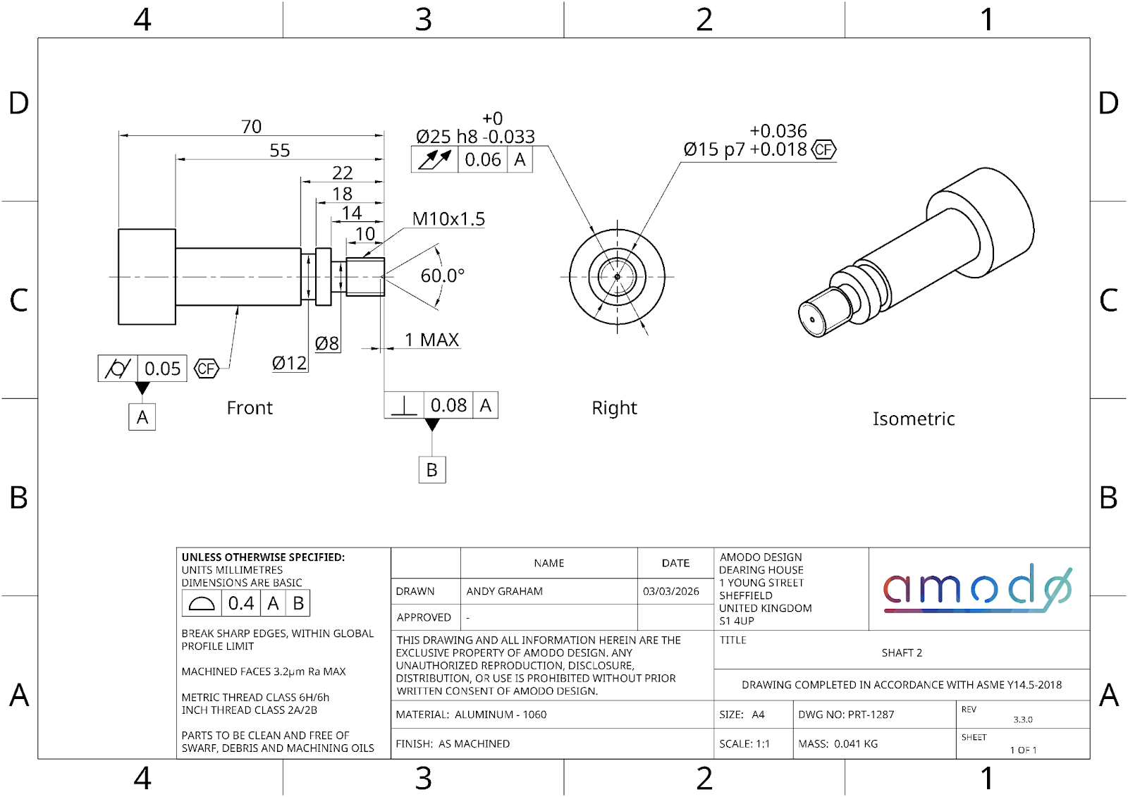
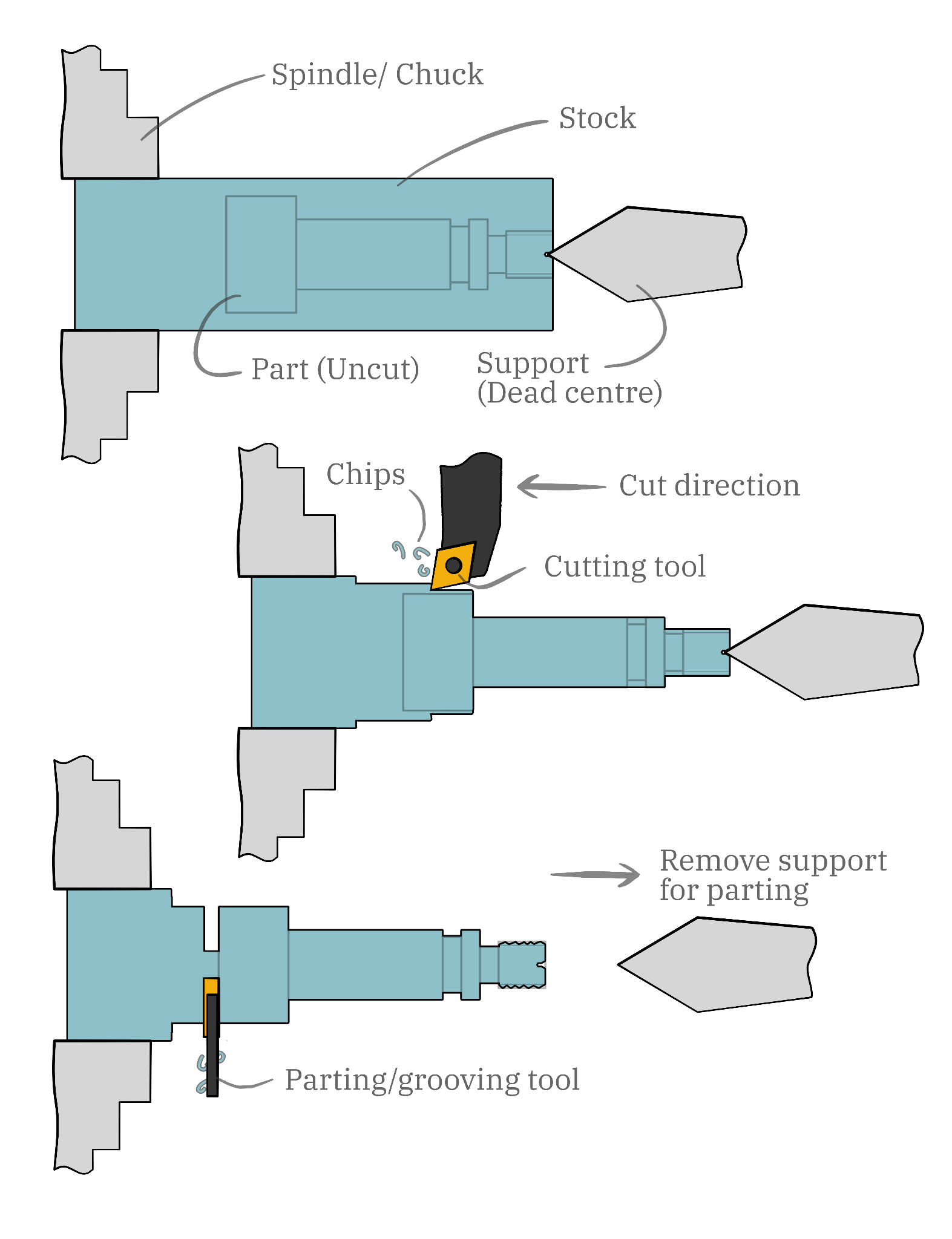
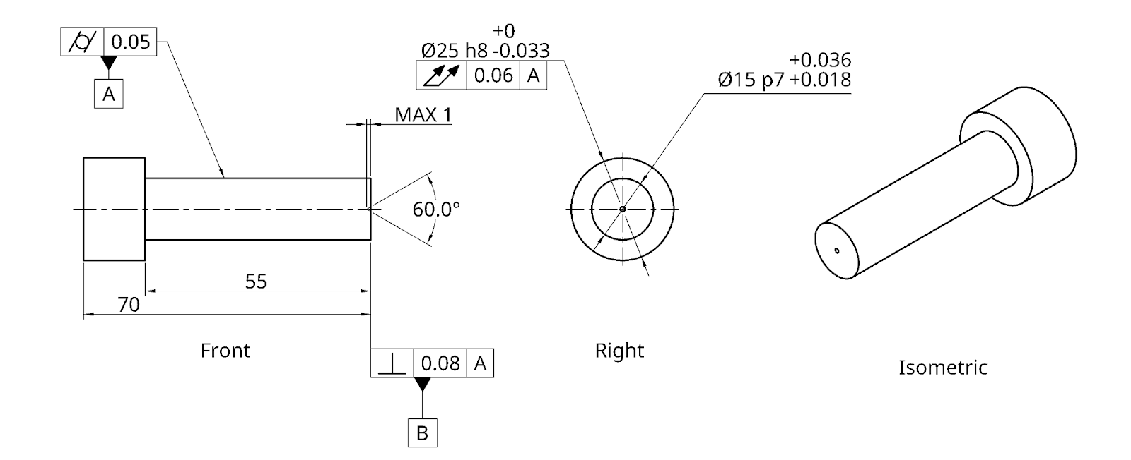
“Machining a part” refers to subtractive manufacture, where you start with a piece of stock (often metal or plastic) and cut away the parts you don’t want, to be left with a finished part. Knowing how to machine a part requires understanding complex geometry from vision alone, then multi-step reasoning about which operations need to happen, in what order, to what tolerance, and how different machining operations might enable or prevent future operations. Example machining process for making the drawing above:
How the evals are built
I built the eval using inspect, AISI’s framework for large language model evaluations. The two questions are based on machining the parts on a lathe, but it would be easy to extend to other equipment.
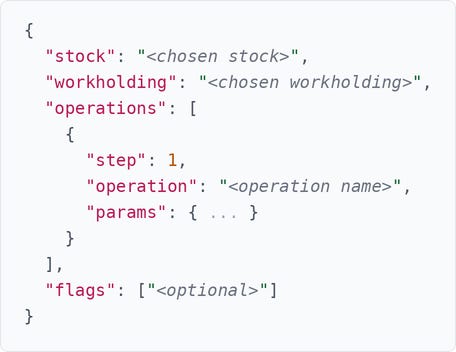
The model is given an engineering drawing and instructed to output machining operations in a pre-defined JSON schema.
Output format
The models were instructed to use a JSON structure:
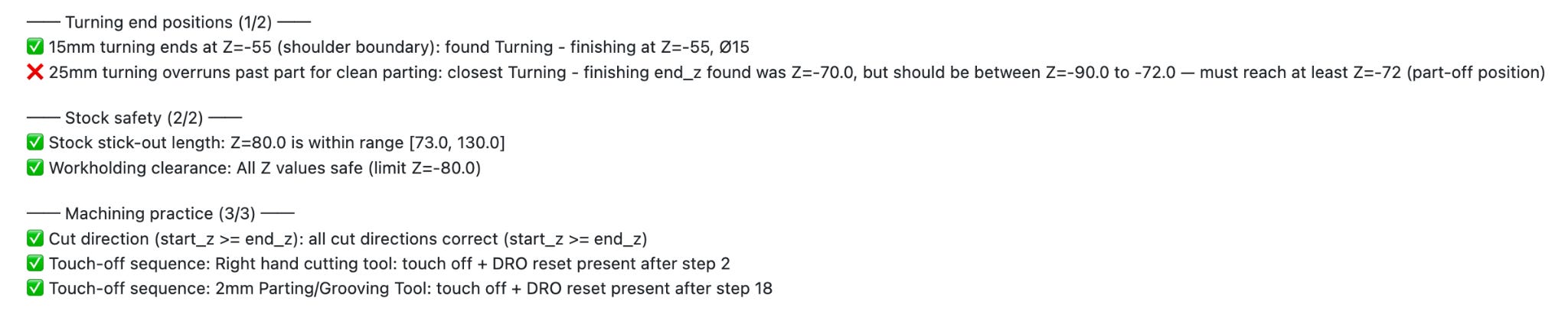
The output is scored against a human-defined mark scheme for things like order-of-operation, tool choice, and operation parameter checks (e.g. start and end z position). Each question has a dedicated scoring module that defines ~30–50 binary pass/fail checks. For example, ordering checks enforce that, when turning, roughing passes come before finishing passes, and parameter checks verify that the finishing diameters and Z positions fall within machining tolerances. The final score is simply the percentage of checks passed.
I spent a while going back and forth to refine the prompts, checks, and tools, to make sure that I was correctly eliciting model capabilities without spoon-feeding them hints and tips. I wanted to capture real errors, not poor scaffolding. The scoring isn’t perfect, but it catches most mistakes.
How good is good enough?
Mistakes in a machining plan usually make downstream operations impossible. If you forget to reset your DRO, all of your subsequent dimensions will be off. If you forget to apply tailstock support, the part deflects and every subsequent dimension is wrong. This means that, in general, a score of 100% is required to guarantee a successfully manufactured part.
That said, not every failed check is fatal. At around the 95%+ mark, some plans contained errors that wouldn’t actually prevent you from making a functional part. For example:
Choosing a four jaw chuck instead of a three jaw. It works, it just takes longer to set up.
Skipping a roughing pass before finishing on a feature with light material removal. You’d get away with it, though the surface finish might suffer (the drawing’s title block specifies Ra 1.6).
These are real mistakes, but they wouldn’t scrap the part. The important thing is that most checks are hard requirements, and the gap between 95% and 100% usually contains at least one plan-breaking error, so most evals with a score under 100% are true failures.
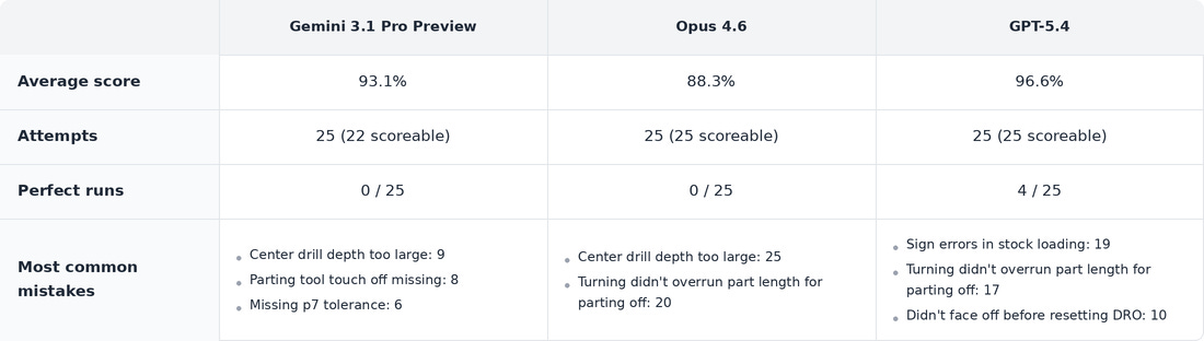
Question 1
Part:
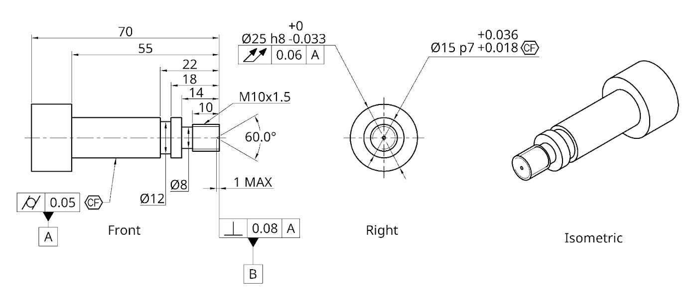
Question 2
Part:
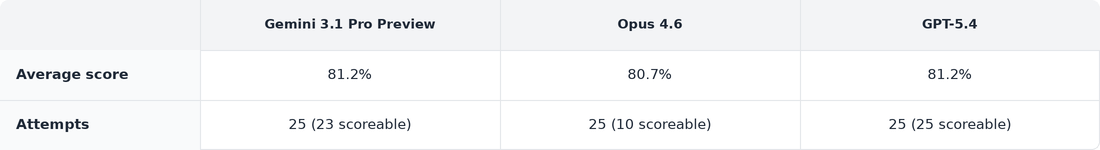
No successful runs on Q2!
The models often failed to provide scorable responses, especially on the more difficult question 2: They appeared to get lost in extended reasoning, also resulting in high token usage. Claude (Opus 4.6) was particularly bad for this.
Despite getting some scoreable results, none of the models had a full working run.
Tidbits
Some things the models did well
Order of operations
Although the models make some order of operations errors, they get the order of operations correct most of the time.
Choosing the correct stock and workholding
I tried to catch the AI out by providing “almost right” stock options, e.g. the 1060 Aluminium: 28mm round bar x 75mm length, which is big enough to contain the parts, with a small-but-sensible buffer on diameter, BUT it only leaves 5mm to hold the part and part off, which isn’t enough. All models caught this every time.
Correctly identifying and finishing to tolerances
All models usually rough and then finish with turning passes, and reasonably consistently aim for the middle of the tolerance band on their finishing passes.
This is particularly impressive when the tolerance isn’t clearly labelled on the feature itself, e.g. the M10 thread, which has a nominal 10mm diameter, but should be undersized in practice to achieve the 6h class in the drawing’s title block, as threads expand in diameter whilst cutting. (The models tended to fail at this but did succeed a few times).
Removing support before parting
This avoids entrapment of the part. It’s a common sense check but neat that they catch it!
Following unusual instructions and oddly marked dimensions
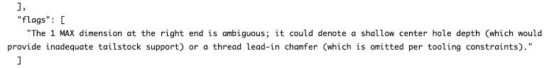
I’ve put an unusually labelled center drill feature in the drawings that is also unusually short (minimum depth for a dead center is typically around 2mm+). The eval prompt allows the models to provide “flags” for review by the designer. You can see below where Gemini has successfully identified the unusual feature, but still correctly created the plan according to the drawing. It also noted that there are no chamfers in the drawing or chamfer tools available.
Some things the models get wrong
Failing to reason about downstream requirements
Example: you need to overshoot by 2+mm in length when turning the outer diameter of a part to provide plenty of room for a clean parting-off. The models sometimes worked these things out, but most models failed more often than not, with Gemini being the exception.
Using the correct operation
E.g. trying to use a cutting tool when a grooving tool would typically be used. This is quite picky of me, but ultimately you shouldn’t be plunge-cutting the right edge of a right-handed turning tool (these traditionally cut with the left edge).
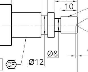
Getting confused about dimensions
The majority of the time the models get dimensions correct, but they sometimes get confused too. One common example is confusing this ⌀12 with the ⌀8 on question 2.
Forgetting operations
Sometimes the models just forget to complete an operation, e.g. applying tailstock support or resetting the DRO after facing, even though they’ve shown they’re capable of using those operations correctly. This happened more frequently on question 2, which was more complex.
It’s worth noting that some of these mistakes, e.g. failing to apply support, cause cascading failure of several downstream checks, so we should expect big leaps in scores once certain skills are consistently applied.
Letting the models review their own work
After starting with one-shot attempts, I tried allowing self-review. The eval would provide the LLM with its formatted response and full history, and ask it to double check it was happy before changing it or submitting as is. The review request was accompanied by three different levels of guidance:
No guidance (just asked to review its response)
“Consider whether the order of operations, parameters, tool selection, and cut directions are all correct.”
20 lines of guidance with hints on common mistakes.
This didn’t improve scores.
What’s next & fun thoughts
For this specific eval, the obvious extensions are more questions, more complexity, and equipment beyond the lathe. Right now, I’m more interested in scoping out different model capabilities around mechanical and electronics engineering. I have several benchmark ideas that I hope to test and write about soon.
Prototyping this evaluation made me think about how you might hill-climb against it. I suspect that there’s an incredible RL dataset buried in dusty, oily hard drives over all the world’s machine shops, pairing engineering and inspection drawings with the CNC GCode used to machine them.
I’ve also been thinking about what’s missing between an AI that can consistently ace an ultra-hard version of this eval and a mostly-automated machine shop. It would be easy to think it’s just a GCODE parser and a huge bank of tools and stock with auto-loading/ejection, but I suspect there will be a load of unforeseen integration challenges.
 | A guest post by
|